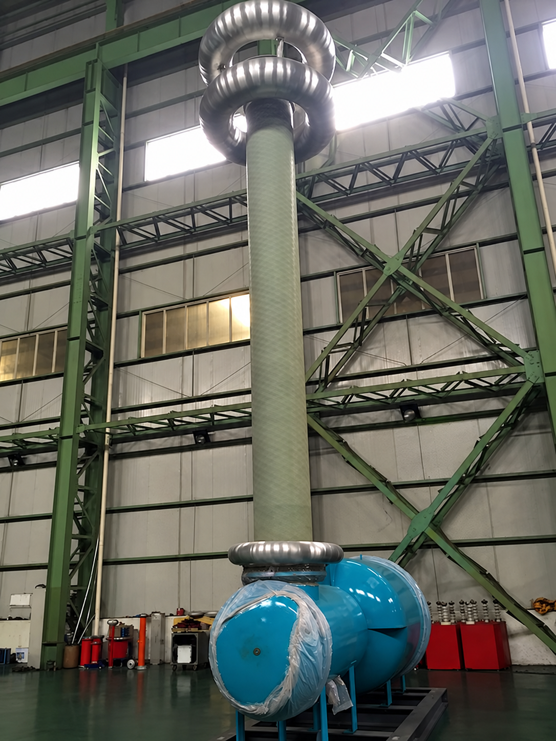

Gas-Insulated (SF₆) AC Test Systems for GIS and GIL
A compact AC source that couples straight into the gas-insulated bus
Gas-insulated switchgear is tested where it is assembled, and the assembly hall rarely has the clearances an air-insulated test set needs. A gas-insulated system puts the test transformer or resonant reactor, the divider and the coupling capacitor inside grounded SF₆ enclosures. The source then occupies a fraction of the volume and couples directly into the GIS instead of through an air-insulated connection.
Output covers 300 kV to 1,200 kV at 0.5 A to 4 A, with capacity from 150 kVA to 3,200 kVA and input at 0.6, 3 or 10 kV. The model matrix runs 300 kV at 0.5, 1, 2 and 4 A, 350 kV at 2 and 4 A, then 450 kV, 600 kV and 800 kV each at 0.5, 1, 2 and 4 A, plus a 1,200 kV unit. Pressure vessels and welding procedures are certified. Where running time or duty cycle is the constraint, a hybrid arrangement pairs an oil-insulated transformer with a gas test chamber.
Why it matters
Source, divider and coupling capacitor are all SF₆-insulated, so the complete measuring chain fits inside a GIS hall instead of a high voltage laboratory.
Coupling through gas removes the air-insulated connection that would otherwise set the partial discharge floor of the whole test.
The matrix from 300 kV / 0.5 A to 1,200 kV covers a single bay through to a full EHV assembly line without a custom design.
Pressure vessel and welding procedure certification is already in place, which is the first thing a factory or site safety review asks for.
A hybrid oil-insulated transformer with a gas test chamber is available where the duty cycle is long enough that a gas-insulated source would need to rest.
Ratings
Voltage: 300 kV to 1,200 kV
Current: 0.5 A to 4 A
Capacity: 150 kVA to 3,200 kVA
Input voltage: 0.6 kV / 3 kV / 10 kV
Model matrix: 300 kV (0.5 / 1 / 2 / 4 A), 350 kV (2 / 4 A), 450 kV, 600 kV and 800 kV (0.5 / 1 / 2 / 4 A each), plus a 1,200 kV unit
Insulation: SF₆-insulated test transformer or series resonant reactor, SF₆ capacitive divider and SF₆ coupling capacitor
Certification: Pressure vessel and welding procedure certified
Hybrid option: Oil-insulated transformer with a gas test chamber, for long running times and heavy duty cycles
Extended range
Supported test sequence: Pre-stressing at approximately (1.1–√3)·Um/√3, one-minute withstand at (1.1–1.5)·Um, and final partial discharge measurement at 1.1·Um/√3
Standards
IEEE Std 4
IEC 62271-203 (GIS)
IEC 60060-1
IEC 60270
Applications
GIS and GIL factory and on-site testing
Gas-insulated switchgear commissioning
Cable accessory testing
University and utility high voltage laboratories
Questions engineers ask
What test sequence does the system support? It supports the standard GIS and GIL sequence: pre-stressing at approximately (1.1–√3)·Um/√3, a one-minute withstand at (1.1–1.5)·Um, and a final partial discharge measurement at 1.1·Um/√3. The SF₆ coupling capacitor stays in circuit for the PD stage, so the sequence runs without rebuilding the connection between steps.
Is a resonant version available instead of a test transformer? Yes. The gas-insulated source is built either as an SF₆-insulated test transformer or as an SF₆-insulated series resonant reactor, with the same SF₆ capacitive divider and coupling capacitor. The choice follows the capacitance of the object: once the GIS or GIL bus is long, the resonant reactor is the efficient option.
+AC+Test+Systems+for+GIS+and+GIL)