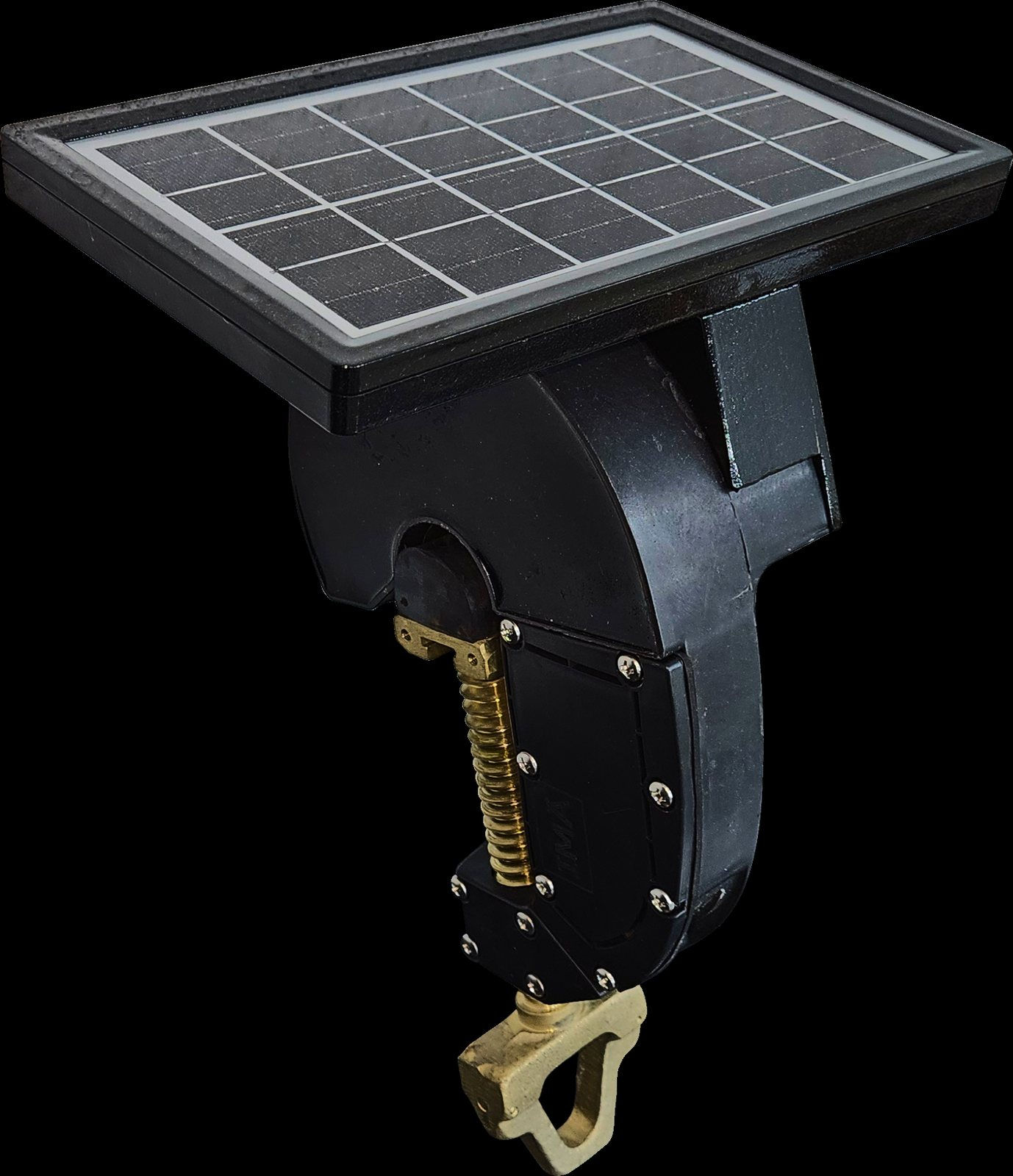

Overhead Line Fault Indicators
Point the crew at the faulted span, not the whole feeder.
An overhead fault indicator is a clamp-on device that watches the conductor and tells you, locally and remotely, which section of the feeder saw the fault current. Without one, a lockout on a long rural feeder means a patrol: a truck driving the line pole by pole while the customer count on the outage ticket keeps climbing. With indicators placed at the branch points, the search collapses to the segment between the last device that operated and the first one that did not.
These units cover 5 kV to 38 kV systems and clamp onto conductors up to 38 mm. The short-circuit trip current is adjustable from 50 to 1,200 A in 1 A steps, so you set it against the actual available fault current at that location instead of accepting a factory default. Earth-fault detection uses a phase-to-ground voltage drop threshold adjustable in 1% steps with an adjustable response delay, which keeps the device quiet through normal system unbalance. The 360° LED reads at a distance from any approach angle, and the radio path — LoRa or NB-IoT to a concentrator, then LTE or 3G to the control room over IEC 60870-5-101, IEC 60870-5-104, DNP3.0 or Modbus — puts the same information in the DMS in about 30 seconds.
Why it matters
SAIDI is driven by how long you spend finding the fault, not how long you spend fixing it. An indicated section removes the patrol phase from restoration time on every permanent fault it catches.
Distinguishing permanent from transient events matters for SAIFI programs. Red blinking for a permanent fault, green for a transient and alternating for an earth fault tells you whether the device downstream is a candidate for a fuse-saving or coordination review.
Adjustable trip current in 1 A steps and an adjustable earth-fault threshold mean one part number covers the head of the feeder and the tail, where available fault current can differ by an order of magnitude.
Installation takes under 15 minutes with a hot stick, live. There is no outage to schedule and no switching order to write, so a full feeder can be instrumented in a single crew day.
−40 °C to +85 °C, IPx5 / IP6x and 31.5 kA for 4 s withstand mean the device survives the fault it is reporting and the winter that follows.
Ratings
System voltage: 5 kV to 38 kV (customizable to 44 kV, 69 kV and 110 kV)
Conductor diameter: Up to 38 mm (6–42 mm range on extended models)
Short-circuit trip current: 50–1,200 A adjustable in 1 A steps, 150 A default
Earth-fault detection: Phase-to-ground voltage drop threshold adjustable in 1% steps, 30% default; response delay adjustable, 30 s default
Maximum load / fault current: 1,200 A
Current withstand: 31.5 kA for 4 s
Accuracy: ±3 A from 0–300 A; ±1% from 300–800 A
Indication: Ultra-bright 360° LED — red blinking for permanent fault, green for transient, alternating for earth fault, yellow for low battery
Alert time: Approximately 30 s to the control room
Reading interval: Every 5 minutes
Communication: LoRa or NB-IoT to the concentrator; Bluetooth for offline configuration; 433 MHz on extended models
Concentrator uplink: LTE / 3G with IEC 60870-5-101, IEC 60870-5-104, DNP3.0 and Modbus
Power: Self-recharging 3.7 VDC battery with solar panel; line-powered CT harvesting with 10-year lithium backup on extended models
Ingress protection: IPx5 / IP6x (IP68 on extended models)
Temperature: −40 °C to +85 °C
Installation: Under 15 minutes; live-line mountable with hot stick
Reset: Manual by magnet, remote by SCADA, or timed (24 h default, 48 h maximum)
Extended range
System voltage: Customizable to 44 kV, 69 kV and 110 kV
Conductor diameter: 6–42 mm range on extended models
Communication: 433 MHz on extended models
Power: Line-powered CT harvesting with 10-year lithium backup on extended models
Ingress protection: IP68 on extended models
Standards
IEEE Std 495
IEC 60255-21
IEC 60529
IEC 61000 EMC series
Applications
Overhead MV distribution and sub-transmission feeders
Fault section location feeding SCADA and DMS
SAIDI / SAIFI reduction programs
Rural feeders with long patrol times
Questions engineers ask
How much can fault indicators reduce SAIDI on a rural feeder?The saving comes out of fault-location time. On a long radial feeder, patrolling to find a permanent fault can take hours; indicators at the branch points narrow the search to one section and report it to the control room in about 30 seconds. Whatever share of your restoration time is patrol time is the share these devices attack.
Can overhead fault indicators be installed without an outage?Yes. The units are live-line mountable with a hot stick and installation takes under 15 minutes each. No outage window, no switching order. Configuration is done over Bluetooth before or after mounting, so the trip current and earth-fault threshold can be set on the ground and verified from the bucket.
Technical documentation
Download HVEX Overhead Line Fault Indicator datasheet (English, PDF)
